|
Tauro 1/48 Macchi C.205V Veltro (Greyhound) - Part II by Riccardo Trotta 
|

|
|
|

Click the STORMO! Eagle to return to the Gallery |
 The engine has been blocked to the relevant section bulkhead, using as references in Figures #3 and #4. For the engine exahusts, I used exhausts made from brass tubes with the help of a friend that builds train models and often uses that material. Passing to the fuselage machine-gun assembly, the ones provided by the kit were used as a base for their elaboration, making them as similar as possible to what appears in Figure #9, details coming from the C205 Catalogo Nomenclatore (Spare parts description catalogue). The machine-guns have been assembled with a stagge, as indicated in Figure #4. The cockpit assembly began with the instrument panel, based on photocolors purchased from another modeler in the second half of the 80s; the photoetched mask provided by the RCR kit S011 was used, after having painted it dark grey, so that the black instruments could be highlighted. The mask profile has been transferred on a plasticard sheet, getting in this way the same surface, on which the instruments coming from a b/w photocopy (reduced of some percent) of the decals provided by the kit, have been glued; the glueing was performed in such a way that every instrument was in correspondence with a mask hole and was included in a white circle. The internal outline of each hole has been previously painted in white. The instrument panel is visible in Figure #13. The lower instrument panel that should be used is the longer one (Figure #15) since the model being constructed is a Serie III°, while the shorter part is applicable to a Serie I°.
Subsequently the oxygen mask provided with the kit was eliminated and the part was scratch built making reference to Figures #17 and #19. With reference to Figure#19, the oxygen bottles have been reconstructed, using some sprue, and the oxygen pipe. Finally, a copper wire was used, winding around it a soldering tin 0.3mm wire; the oxygen mask was constructed with plasticard.
The cockpit detail was continued using Figures #14, #15, #16, #18. The cockpit was painted in Verde Anticorrosione used by Aermacchi, corresponding to FS 34558, according to the last issue of the book “Colori e schemi mimetici della Regia Aeronautica 1935-1943” issued by G.M.T. – C.M.P.R. - G.A.V.S. page 122; as I have also the first issue (1979) with the color chips, I used the chip as a reference and reproduced the color with the following receipt, based on Tamiya colors: 8 pp XF21+3 pp XF23+ 4pp XF2+ 1 pp XF5, a mixture that can be easily prepared using graduated syringes.
The cockpit floor was painted in aluminium as well as the rudder pedals, RCR photoetched parts were used. On the contrary, the seat structure and the control stick were scratch built. The oxygen mask was painted in blue, while the oxygen pipes are white (Figure #20), in compliance with the official prescriptions referred to in the above mentioned book page 68; also the oxygen bottles have the higher part painted in white, as shown in Figure#23, which concerns the same installations on a C202; Figure#23 is useful also to see the seat structure, the same on both the C202 and C205. The seat belts are from RCR photoetched kit S016, while the protective headrest plate comes from RSC S011. So the internal work was completed (Figure #21 and #22).
Consequently the two half fuselages were then glued, omitting for the moment the phase before the engine mount section; the following activities were performed: • Thinning cowling where the gratings are present, re-engraving the slits of the gratings and the circular ports, painting of the internal surfaces and glueing. • Glueing the engine exhaust slit to the lower part of the nose (left side of the fuselage; the right side, at this point has already been glued, as mentioned above); this phase is a little delicate, because gluing is to be performed in such a way that the front part of the nose is in compliance with the drawing; use putty and work with sand paper will be necessary subsequently. • Gluing the part that interfaces the spinner rear disc, in such a way to have a valid reference for the cowling fit. • Cowling adaptation, reconstruction, scribing and air intakes opening (Figures #26 and #27).
• Thinning of the cowling, working on the internal surface, and the construction of the internal structure with Evergreen strips (or equivalent); a view of this structure can be found on page 43 of the above mentioned Aerodetail #15; on the basis of these images also the grooves for the nose machine guns can be fitted. • Open on the right side of the cowling an oval opening 2 mm long and maximum width 1.2 mm (Figure #29).
• The sand filter provided by the kit is not very satisfactory; I preferred to reproduce it in resin using as master form the one provided by the Hasegawa kit. • Positioning in compliance with the drawing of the oil filters; for the internal gratings, details provided by the above mentioned RCR kit can be used. • Positioning of the engine exhausts on the left side, construction of the fairing and of the relevant connection. • Air filter positioning in such a way that the cowling is removable; verify the correct fit of the cowling to the fuselage and performing the necessary corrections (if any). • Lower wing: as already reported, the landing gear bay is over dimensioned by about 1.5 mm; the correction is to be performed using plasticard strips on the straight part, where the engine mount bulkhead leans. • On the lower wing, eliminate the separation fillets between the flap sections. • Correction of the vertical rudder profile (higher profile, fin junction line, hinge bay). • Fin thickness reduction, in such a way to have correspondence with the rudder thickness, using wet sand paper, saving the engraving with a point. • Rudder fabric reconstruction with Evergreen strips 0.5x0,25 mm, glued on edge and subsequently reduced with sand paper. • Opening of the case exhausts of the wing guns on the wings lower surface (Figure #28). • Reconstruction of the wing fuselage front joint at the wing root.
• Scratch building of the landing gear bay closure, using the blisters from medicine packaging, putty and plasticard; with reference to Brioschi’s post (on wardbirds in scale forum, if I correctly remember) dated January 10th, 2003, where he refers his research to Aermacchi and Breda, I painted the internal surfaces of the landing gear bay in Grigio Azzurro chiaro (light blue grey). • Following the assembly of the lower wings, the position of the landing gear has been verified, expecially the slope, and subsequently they have been glued. • Setting of the rear part of the wing fuselage joint, at the fuselage joint. • The wing gun ports did not have a rectangular profile, but the shape of a rectangle with rounded corners (Figure #24); a profile in transparent acetate, to have a correct positioning, has been prepared and the ports shape on the upper wings surface has been corrected.
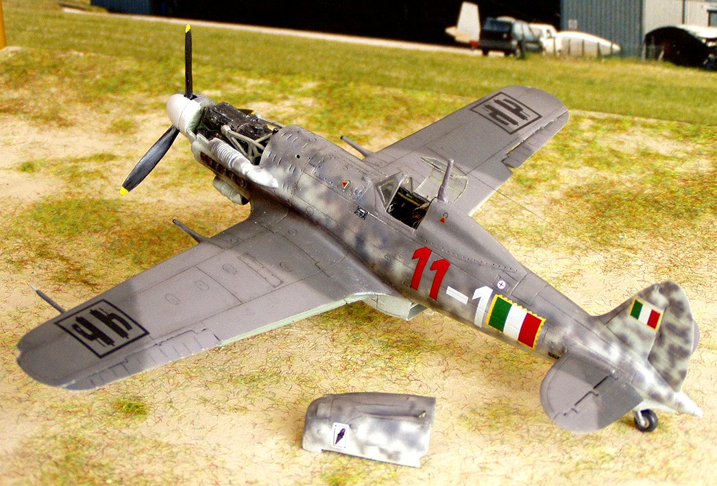
• Construction, using Evergreen rod 1.2 mm diameter, of the small aperatures in correspondence of the case exhausts on the lower wings (Figure #28). • Drill a small hole for the oil filter ventilation on the left wing root, (Figure #2). • Scribe on the higher surface of each wing, at the wing root, a circular port 2 mm diameter for the tank access; these ports were already present on C202. • Connection on the wing entrance edge, using a point, of the engravings of the higher and lower wing surfaces. • Drill a hole, according to the drawing, on the fuselage starboard to subsequently insert and glue the Venturi tube. • Construction and assembly of the connection plates of each half wing to the fuselage, both for the lower and upper surfaces. • Water radiator: the one provided by the kit has the lateral sides incurvated; for the correction, the radiator has been cut lenghtwise and glued after the insertion of little plasticard wedges and has been subsequently refined using plasticard and putty; the internal surfaces have been detailed using the details from the RCR kit. • The tail planes need some correction using a file, to be in compliance with the drawings and need some plasticard insertion between the movable and fixed parts and putty at the fuselage connection. • Wing ailerons: it was necessary to construct the ribbing on both surfaces, using Evergreen strips 0.25x0.50 mm, glued on edge and subsequently refined with sand paper. • For wing ailerons position it was necessary to first reduce the step between the upper and lower surface of each wing, using sand paper. • Flaps: the separation between the two sections has been eliminated and the correct length has been restored. At this point the painting phase has started; the selected subject is the “Red 11” of the Squadriglia Asso di Bastoni of ANR; the Figure #25 and #30, from the CMPR archive, shows the same subject from two different points of view, but allows to see well the camouflage shape in German colors 74-75-76, which starts on the upper part of the cowling, coming down with shade on the fuselage, dropping to the wing connection in corresponce with the cockpit, letting the background color 76 to shine, and restarting to climb up towards the tail; all the camouflage on the fuselage appears in 75, with little mottles in 74 in the zone where 75 reaches the wing root; it was not possible to find images showing the wing camouflage, so the images from the D’Amico –Valentini book “Camouflage and Markings of the ANR 1943-1945” were used as example.
The camouflage colors are Gunze H69 for RLM 75 and Gunze H68 for RLM 74. For RLM 76 Gunze H314 was used, similar to FS 35622, using as a reference a piece of a wreck of a Me109, flown in 1944 (the same year of the representation of the model of the C205) near the Gothic line and visible in the Gothic Line museum at Montemurlo (Prato); this detail points out the light blue shade (Figure #31).
In order to get a dependable reproduction (at least in my opinion) of the shade of RLM75 on the fuselage sides, in the zones of feathering RLM 76, the RLM 75 is air-brushed very thinned. At this point the landing gear was assembled; the slots for the legs present on the covers are to be deepened, in such a way that the distance between the vertical axis of the leg and the surface of the coverage is » 3 mm. These slots are also to be displaced: for instance the lowest has to rest on the upper part of the fork. Furthermore these slots are to be detailed with light holes to allow the crossing of the tube of the brake oil (Figure #32).
The wing guns come from a Hasegawa kit, used to represent a I° series. After having assembled the Venturi tube, a transparent gloss is air-brushed to position the decals; the red 11 comes from two boxes of the Tauro kit (which provides the codes 18-1); the other decals comes from the ones proposed by the kit and the Skymodels sheet dedicated to C205. The dimension of the fuselage flag is interesting: as it is possible to see from the image, its upper profile is in line with the numbers upper profile and it lenghtens to about 2/3 of the length of the numbers; in other photos of airplanes of the same squadriglia the flag dimensions appear reduced and the postioning seems lower. The fasces on the wings are black; according to the historians D’Amico and Valentini, the lonely airplane that had the white fasces was the one code 18-1, which is unique with the code 18-1 on the port side and 1-18 on the starboard side; on all the other airplanes the red number always preceds the white one, in the reading direction. The panels have been lightly highlighted with sepia ink and all the model has been lightly weathered, as it appears in the photos. The completed model appears below. Particular thanks to Mr. Giorgio Di Giorgio, CMPR Manager. Riccardo Trotta CMPR – IPMS – Gruppo Plastimodellismo Fiorentino 


|
Aircraft: Macchi C.205 Serie III Manufacturer: Aeronautica Macchi S.p.A. Type: Fighter Year: 1943 Engine: Damiler Benz DB 605A-1, 12-cylinder V, liquid-cooled 1,475hp Wingspan: 34 ft 8 1/2 in (10.59m) Length: 29 ft 1 in (8.85 m) Height: 10 ft (3.05 m) Weight: 7,120 lb (3,224 kg) (Loaded) Maximum Speed: 403 mph (650 km/h) at 24,300 ft (7,400 m) Ceiling: 37,200 ft (11,350 m) Range: 646 miles (1,040 km) Armament: 2 x 12.7mm (0.5 in) SAFAT machine guns, 2 x 20 mm cannons Crew: 1 |
|
|
|
|
|

|
|
|


|


 - Scale 1:48 - UC48176")

|
|
|
|
December, 2007 STORMO! © 2007 |


