|
Airfix 1/72 Savoia-Marchetti SM.79 II Aerosilurante Ace - cap. C. E. Buscaglia by Bruno Perfetto |

 |

Click the STORMO! Eagle to return to the Gallery |
|
Introduction For every modeller there certainly exists a subject that more than any other goes beyond modeling value. For myself, this is undoubtedly the "Damned Hunchback". It would be out of place here to express what this subject is able to convey to me, but observing my finished model I cannot forget when I had the opportunity to get on board in the unreal silence of a museum, trying to imagine what those who demonstrated on this machine had experienced what Value is. I therefore owe a sincere thank you to the people who in recent years have been able to teach me something that I will never be able to read in any history book. Observing this model I continue to experience these sensations and for this reason, beyond the work done for its creation, I consider it a successful model. Model Study For historical reasons I wanted to represent the captain's plane, cap. Carlo Emanuele Buscaglia when he was in command of the 281st Torpedo Bomber Squadron based in Gadurr� in 1941. The kit used is the old Airfix. The plastic is very soft, perhaps too soft, and therefore easily workable, although in the example in my possession, although it seems not to be an isolated case, it tends to peel and/or come off in flakes during processing. The details are those of a �70 year old kit, so the interiors are really rough, the surface details are rough, etc. For accurate work, the model will have to be revised in numerous points, while for those who decide not to go too far, only a few structural corrections are sufficient. The decals are the only part that have undergone an improvement in the re-edition, although it will certainly be preferable to replace them. Before moving on to assembly, a piece of advice for anyone who intends to tackle an extremely accurate job: the modeller must be absolutely clear about the position of the three structural spars. These, as in the real aircraft, are the fulcrum of the model as only on the basis of them is it possible to correctly position the various parts inside the fuselage (such as the structural tubing, the pilot cabin and the radio operator's station, etc.) and also those relating to the wings (undercarriage spaces, engine mounts, etc.). Unfortunately, this aspect, which is anything but a detail, is not easily understood either from the drawings available or from the photos of the aircraft. |

|

|


|

|

|
|
|
Exterior Fuselage Assembly begins with modifying of the two half fuselages. The length must be rectified by shortening it by 3 mm: the two half fuselages must be sectioned vertically immediately in front of the attachment of the horizontal tail planes; once the excess part has been removed, the fuselage sections must be rejoined by aligning the external surfaces as much as possible. By doing so, the external ribs are partially ruined, but they can be repaired with skilful grouting and sanding. Personally I preferred to completely redo these ribs, a characteristic detail of the "Gobbo", also because they were incorrect in the kit. I then sanded the external surfaces perfectly and, referring to the documentation, I engraved some grooves corresponding to these ribs with the specific Squadron tool. Pieces of copper wire with an adequate section were stretched and then placed in these grooves, so as to protrude for approximately a third of their section. They were then filled and sanded appropriately, to obtain a not too pronounced effect at the end1.
The internal sides of the rear areas of the two half fuselages were then sanded as the kit does not faithfully reproduce, in my opinion, the line of the "Gobbo". The fin was also modified, detaching it from the fuselage to thin its internal walls and reconstruct its ribs. Furthermore, the front areas of the two half fuselages were sanded, where the squared section of the fuselage becomes almost round to connect with the engine cowling, in order to give the model a less "heavy" line. Still in this area of the model, I eliminated the 5 mm of the front part of the half fuselages. In fact, this area poorly reproduces the conical covering of the engine mount which, albeit barely perceptibly, surmounts the fuselage. At the rear, the areas relating to the two side doors of the small wheel have been eliminated2. These areas in the model do not reproduce the curvature that characterized these doors.
Further forward of the bomb bay, the compartment for the landing light was modified by squaring it at the front, having decided to leave it in the open position at the end. Still remaining on the belly of the fuselage, the windows have been opened in correspondence with the claiming nacelle which are completely absent in the kit. Further forward, on the right side, the trapezoid-shaped camera door has been engraved. In the fuselage, all the rectangular windows have been moved forward by 1.5 mm, while the windows for the machine guns have also been moved forward by 1 mm and upwards by 1 mm. In the upper part of the entrance door, where the door was attached, the gap was reduced from three to one millimetre, while in the lower part the gaps were created for the rotation hinges of the door itself. The rigid parts of the hump were then eliminated from the two semi-fuselases, having decided to use the thermoformed one from RCR/Falcon. |


|
Interior Fuselage The internal surfaces of the model have been significantly thinned in order to obtain a credible thickness. With the support of all the available documentation, I then began a long process of building all the internal structures of the aircraft, both those relating to the walls and those that go diagonally from one wall to the other, using copper wires of various sections and Evergreen profiles. The latter were also used, drilled with a 0.1 mm tip every millimetre, to build the side spars of the fuselage which, seen from the outside, are nothing other than the ribs mentioned above; therefore their positioning must be carefully studied. On the other hand, the slightest error has repercussions on the entire reconstruction work of the structure. Both the positioning of the ribs and the structures surrounding the windows or the various openings in the fuselage can certainly be of help. It is a meticulous job that requires careful preliminary study, but the results I have obtained largely satisfy me. Starting from the nose, the firewall was redone which is visible beyond the pedals, the cockpit floor which has a different inclination going from the pilot cabin to the radio operator/machine gunner's area, the vertical wall which connects the bomb hold with the floor of the passenger compartment. Precisely at this point the support for the control levers and the fuel level pipes (Televel) was created3. If, as suggested at the beginning, the position of the spars has been carefully studied, both the bomb bay and the entire front cabin will find their right location.
Photo-etched seats were used for the radio operator and engineer positions. Certainly the most demanding part of the detail work on the interior of the fuselage is the reconstruction of the pylon to which the bomb baskets were fixed, on the bombing versions, which differed depending on the type of bomb transported. It should be noted that the bomb bay doors had "plugs" which were removed when the 250 kg bombs were mounted as they protruded with their tips from the belly of the plane. This truss was made of copper wire and detailed with bomb hooks and control wires. On its left side there was a small walkway that was used by the specialists during the bomb placement phases 6. To the side of the bomb bay there is the walkway that connects the pilot cabin with the rear part of the fuselage. On the wall of the fuselage, in correspondence with this walkway, there was a wooden covering, reproduced with a piece of plasticard, which probably served to avoid entanglement in the structure of the aircraft.
The floor in the fuselage was completely redone, leaving aside the one supplied by the Eduard set as it was insufficient. In the real aircraft the floor was covered with finely corrugated non-slip sheet metal and was in a single piece along the entire fuselage, from the walkway on the side of the bomb bay to the pointer nacelle. Similarly, the step between the aforementioned walkway and the radio operator/engine engineer's area, the walkable parts in correspondence with the side machine guns, inside the pointer's gondola and the walkway at the side of the bomb-holder pylon were created. All these areas were reconstructed with very thin plasticard on which an aluminum sheet for food use was glued after which, in order to reproduce the anti-slip effect, it was treated in the following way: placing this sheet on plastic for electrical purposes with a finely lined surface, with a tooth polishing brush kindly provided to me by my dentist, mounted on a drill, I went over the aluminum sheet itself, practically transferring this wave-like pattern onto it: the effect obtained is extremely realistic. Another characteristic detail of the internal structure of the Gobbo are the control rods of the tail planes and the rudder8. Everything was made, needless to say, in copper wire and plasticard. The positioning of the rods must be carefully studied, especially in correspondence with the bomb-holder pylon, also taking into account that the two rods do not run on the same latitudinal plane. Lastly, the pointer nacelle. This is, in my opinion, one of the parts that is less clear to those preparing to build an SM.79. On various models that I had the opportunity to observe at exhibitions, I noticed how this part was reproduced incorrectly or, perhaps due to lack of adequate documentation, summarily9. In this case the photo-etched pieces were good enough to reproduce the part that allowed the pointer to sit in front of the "typewriter" - even if the whole thing turned out to be 1 mm too wide and was therefore reduced - while the leggings were reconstructed in brass sheet. The glazing is made up of four pieces: two lateral ones with a trapezoidal shape, a rectangular one in the lower part under the aiming system and a rectangular one placed at the front. So the gondola at the front, without the protective part, is square! The piece of kit that reproduces it is completely incorrect and several modifications must be made to it. First of all, the curved front part, integral with the rest of the gondola, must be removed; the curved lens supplied by the kit can definitely be set aside as it is too thick to reproduce the protective screen. After removing the curved front part, a further 5 mm must be eliminated, in place of which the square structure on which the glazing is to be mounted must be recreated. Furthermore, after cutting the part relating to the opening doors, the section of the entire gondola must be modified; in fact, while the kit piece is entirely squared, in reality the section went from squared at the front to curved at the rear. The operation is feasible thanks to the thickness of the plastic, working on both the internal and external areas. The same applies to the two opening hatches, on which the internal reinforcement and the recess from which the machine gun protruded in the rest position will also have to be rebuilt10. All the various details of the gondola were reproduced with copper wire of various sections, plasticard and brass sheet. As already mentioned, the walkable part was also rebuilt with the same procedure followed for the fuselage floor. |


|
|
Interior Painting All the interiors were airbrushed first in Verde Anticorrosione (Xtracolor X120 � FS14258) and then in medium gray (Xtracolor X138 � FS16473), trying not to cover completely with gray but allowing the green to appear in the gaps11. Light stains were then carried out with a brown oil colour, in order to darken the interstices (unfortunately the photos enhance this effect compared to reality), and with a dry brush in very light gray to give depth to the whole. The Tail As mentioned, the fin was detached from the half fuselages to reduce its thickness and to recreate the characteristic ribs. The rudder hinges were removed and redone correctly. The vertical rudder has also been thinned, the shape of its upper part has been corrected - rounding it more - and the recesses for the hooks that connect it to the centerboard have been redone; the vertical trim of the rudder was detached, obviously not following the lines proposed by the kit as they were incorrect, and repositioned well detached from the rudder, as can be seen in the photos of the time. Furthermore, both on the rudder and on the tail of the fuselage, on both sides, fairings for the trim control cables have been added. The ribs have also been redone on the rudder. The fixed horizontal tail planes have been significantly modified: 2 mm have been eliminated from the external part and the front part has been revised, eliminating from 0 mm at the junction with the fuselage up to 2 mm in the external part. Furthermore, they were obviously thinned and the ribs were redone, also adding a strip of plasticard in the lower part where the support beams attach to the fuselage. The movable horizontal planes have been resized accordingly and the internal side profile has been modified: in fact they are not squared as proposed in the kit, but are more rounded and protruding towards the horizontal rudder. They too received the ribbing. Both centerboard and horizontal fixed planes12 they were connected with putty in the areas where they join the fuselage. The tail end was modified making it more rounded with the addition of putty. On its terminal, the white position light was added during the finishing phase. The wheel doors were remade in sheet metal giving them the necessary camber. Landing Gear Bays They are certainly a delicate part of the model as the correct arrangement of the engine mounts and the engines themselves depends on them.
The profile of the gear bays shown on the gondolas must be modified by making the rear part circular and the areas to which the doors will be joined straight rather than curved. The wing spars and structural beams are made of plasticard of various thicknesses, while the bottom, which corresponds to the surface of the wing, is made of sheet metal. The internal reinforcements are instead in copper wire, while the details, few, are in sheet metal and plasticard. Details relating to the area between the undercarriage compartment and the engine flameproof bulkhead have also been added, such as the oil tank section, load-bearing structures, petrol pipes and control rods. Very useful in this regard was GMT news bulletin no. 3 where the engine mounting on the ground and the relative fixing point with all the relevant details are photographed. Finally, it should be noted that the relief observable on the upper surface of the wing, immediately in front of the stern tube tank, is a recess made in the undercarriage compartment to allow the feedback jack to complete its complete movement. The closing doors have been modified, making them also straight in the upper part and bringing the recess forward by 3 mm to accommodate the wheel; furthermore they were thinned on the internal part, on which the lightening holes and riveting were made, and they were externally covered in sheet metal. |

|
Landing Gear First of all, the framework that rests on the first and second spar was created. The gear bay was then mounted on this (completely self-built with plastic tube, plasticard, copper wire, etc.). The support rods and the feedback jack were then added between the gear bay and the third spar. Note how the latter has no "bare" areas; on the model the coverings are made of handkerchief-type paper soaked in cyanoacrylate glue. The beautiful wheels are those from the PD Model set and the wheel hubs are made of tubular steel. The Wings Not even the wings are free from defects. First of all, the minimum wing chord is correct while the maximum one is too wide, even if it is difficult to measure as the wing-fuselage fairing is integral with the latter13. This defect is easily eliminated by removing, after removing the flaps from the upper and lower wings, 2 mm from the wing trailing edge: the wing will then be joined to the fuselage by aligning it at the rear with the fairing, of which the excess front part will be removed14. Obviously you need to pay attention to the alignment of the wing so as not to rotate it on the horizontal plane. Clearly, by eliminating 2 mm from the trailing edge, it will be necessary to adequately taper the wing in order to give a very thin trailing edge. This is possible thanks to the thickness of the plastic and for uniformity it must be carried out along the entire longitudinal axis of the wing. The other main flaw concerns the distance between the two lateral engines15. The axis of each of the two lateral engines must be brought closer to that of the fuselage by 2 mm and the excess part must therefore be eliminated between the fuselage and wing. Consequently, the wing tips will have to be lengthened by the same size, thus giving them a circular profile16. The changes just described can be made thanks to the fact that the maximum chord is too wide and therefore, keeping the leading edge unchanged, the ailerons and flaps and the relative housings will have to be sized appropriately. Note in particular how on the upper wing there is, between the flap (internal) and the aileron (external) housing, a minimum step of the order of 1/10 of a millimetre, while on the lower wing this step is equal to a millimetre. The flap and aileron housings were closed, between the two wings, with a portion of a straw for drinks. The fairing between the wing and fuselage also needs to be revised, as it is decidedly incorrect as proposed by the kit. Following the drawings, you will need to add putty until the correct profile is obtained. The shape of the stern of the engine fairing must also be modified, adding the fittings with the wing trailing edge. The entire wing surface must be sanded in order to make it perfectly smooth, as the plane was covered in wood. An exception is the paneling of the tank contained in the stern of the engine fairing and the caps of the wing tanks. The panels relating to the inspection caps must also be recreated on the lower surface. The drawings in the Ali d'Italia volume are excellent for this purpose. Lateral Engine Structures The motor mounts are entirely made of copper wire of various sections, including the ring to which the motor will be fixed, which has been sanded to give it a square section. To correctly create the engine mounts it was necessary to have a clear understanding of the measurements of all the pieces that compose it in order to drill the 17 mm diameter plasticard disk representing the flameproof bulkhead in the right places. As in reality, the engine mounts were fixed to the gear bay truss mounted between the first and second spar and on the first spar itself. This is so that the structure created is sufficiently robust to support the engine. The pipes that convey oil and gasoline to the engine, as well as the pipes and relative tank of the gyroscopic system, were then added to the flameproof bulkhead17. Engines At the beginning of its operational career, the SM.79 was fitted with the Alfa Romeo 126RC and later, adopting its evolution, the Alfa Romeo 128RC. The differences between the two engines are notable:
Finally, a detail which is not negligible from a modeling point of view, on the 128s and only on some 126s (evidently depending on the evolution of the engine) there were two small horns on the front part, on the sides of the upper cylinder. Therefore, pay attention to the specimen that reproduces.
A plasticard disc with the relative bolts was then added to the rear of the engine, with modeling freedom to ensure safe fixing, which allows the engine to be mounted on the mount. This is because the engine is quite heavy being made of metal. Also completely home-built, again in the engine without hood, is the carburettor-pump unit located on the back of the engine itself. The carburettor, the oil and fuel pumps, the two magnetos with the relative cavities and the three air intakes located under the carburetor were made with plasticard, copper wires of various sections and sheet metal. Everything was carefully fixed on the rear part of the engine after it was mounted on the mount.
Only after the model had been painted, the engines were fixed to their seats and, after having positioned the cowlings - only the exhaust ring for the bare engine - the two exhaust pipes per cylinder and the support rods of the exhaust manifold to the engine body. Before their installation, the engines were painted in Exhaust Xtracolor X504 on which a silver drybrush and a brown oil wash were carried out. The engine cowls are from the PD Model resin set. They are really well made and only the paneling has been highlighted19. For the open engine, only the front exhaust manifold was obviously retained. The exhaust pipe (the one with a constant circular section) was added to the three engine hoods with a shaped and filled plastirod. On the open engine, the fixed part surrounding it was also added to the exhaust. The cowlings were painted the same gray as the front part of the plane (see below), while the exhaust manifolds were painted copper and silver in the innermost part. Other Details The weapons are taken from the Aires set for the 12.7mm Browning machine guns, modifying them to reproduce the Safat. The mouths applied to the carriages are different in order to differentiate the 12.7mm from the 7.62mm. The fixed machine gun was not mounted in the hunt as it is clearly visible that this was absent on the real example to save weight. The hole on the hump was blocked with brass sheet. The weapons were deliberately left without their shell holders and related ammunition boxes. The color is in Gun Metal Xtracolor with graphite drybrush. |


|
|
|
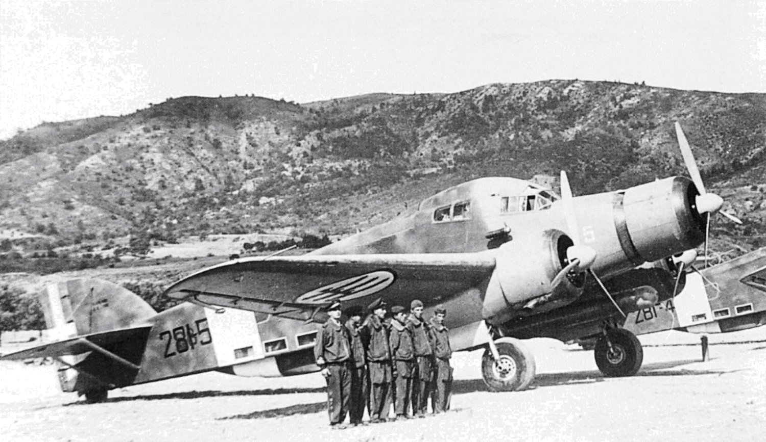
Painting the Model The camouflage scheme of the 281-5 is, referring to the volume Colors and Mimetic Schemes of the Regia Aeronautica � 2nd ed., the C1 scheme, i.e. lower surfaces in Grigio Mimetico (Xtracolor X131) and upper surfaces in Giallo Mimetico 3 (Xtracolor X209x5 + X213x2 + X141x1) with patches in Marrone Mimetico 53193 (Humbrol 29x5 + 60x4 + 98x2) and Verde Mimetico 53192 (Xtracolor X 148) which, unlike the sample reported in the aforementioned volume, have been left sparser and more nuanced. The front part of the aircraft, including the engine hoods, nose cones and propellers - the rear parts of the blades are black - was painted in a slightly darker gray than that applied to the lower surfaces, based on what can be seen in the photo on page. 22 of n� 11 of Ali d'Italia. This is unlike the other SM.79s visible in the photo, deployed alongside Buscaglia's plane, where the front gray is slightly lighter than the lower surfaces. You can also see in this photo how the fairing of the central engine mount is certainly not gray nor in the colors of the plane's camouflage. Personally I opted for Verde Oliva Scuro with Grigio Mimetico on the bottom. The white band on the fuselage was made in very light gray FS16622 (Xtracolor X140).
Final Details The model is completed with the assembly of the Pitot tubes, the wire antennas and that of the radio direction finder. The Pellizzari auxiliary generator is also mounted on the right side under the pilot cabin. At the end, all the hatches are mounted, including the bomb bay hatch kept open by a rod and the entrance hatch appropriately offset from the opening in the fuselage.
It makes little sense in my opinion to represent a torpedo bomber without its main weapon. After carefully avoiding the torpedo pieces supplied by the kit, I proceeded to build it myself starting from a copper rod with a diameter of 6mm. In my case the ends were obtained from an old torpedo from an Airfix kit dedicated to a Beaufighter. The CMPR 4/90-1/91 newsletter is essential for the construction of the torpedo. The torpedo empennages (the Eduard ones are incorrect) as well as the blades of the two propellers and the additional rear empennages are also home-made. Control rods were also added to the torpedo. The trolley was created in a very simple way by referring to the few photographs available on it. The torpedo was painted in Testors Magnesium. The warhead was coated with graphite and SNJ powder while the body of the torpedo was dirtied with brown oil paint20. The additional empennage was painted in very light gray FS16622 (Xtracolor X140). The trolley, however, was painted in medium gray and generously aged with brown oil paint and light gray drybrush. |


|
References 1 Consulting the photographic material, various aspects are observed: first of all, the photos of aircraft in flight should not be considered, where the air moved forward by the aircraft compresses the fuselage surfaces, highlighting the ribbing effect; among the photos of planes taken on the ground, various ribbing effects are observed, regardless of the inclination of the light. In particular, in some photos the ribs are barely noticeable, in others they are clearly visible and/or you can even notice a riveting in correspondence with the ribs themselves. This probably depends on the version of the plane (in the RSI photos they seem more evident to me) and by which manufacturer the plane was made. In the majority of photos this effect does not appear extremely evident in any case. 2 These opened pushed by the wheel itself when it maneuvered and closed again thanks to a spring that made them fit to the fuselage. 3 From this point the fuel tanks could be controlled, for which a precise consumption table was provided in order to maintain a balanced attitude of the aircraft. Furthermore, individual tanks could be excluded in the event of failure or a transfer from one tank to another. The pilots preferred, when possible, to leave the central fuselage tank empty as it made the aircraft much more vulnerable: cap. Faggioni was shot down as this tank was hit directly. The same support was also used to mount the cartridge belt for the rear-firing machine gun and the relative collection bag for the cartridge cases. 4 These were actually very Spartan, being made up of a tubular structure covered in the headrest area, but this is not always the case, and immediately above the cushion with a green canvas. 5 The AR.8 receiver, the A.350/1 transmitter and the P.63N radio direction finder were mounted on the SM.79. 6 As is known, the bombs were hoisted from below inside the hold by means of a winch fixed to the pylon itself. In the torpedo version, the bomb bay obviously remained empty. Indeed, it was Buscaglia who, to increase autonomy, at a certain point decided to mount an additional tank obtained from a wing of a CANT Z.1007, a device that became standard on the RSI SM.79bis. 7 This tank had to always be full and was able to power the engines by gravity, obviously for a limited time, in the event of a failure in the electrical system thanks to which the fuel pumps worked. 8 These start from the pedals and the handwheels, under the floor of the pilot cabin, and come out at the wall next to the co-pilot's seat, continuing diagonally up to the joints located at the height of the front part of the bomb rack; from these joints they continue, passing through the structures that support the pylon itself, almost up to the height of the trapezoidal fuselage window where, through joints, they are brought to the center line of the fuselage and then continue towards the tail rudders. Note that the handwheel present in the pointer station is connected, again by means of rods and joints, to the rod that regulates the vertical rudder. 9 In reality the mechanism was very simple. The curved front part was a protective screen for the glazing that the pointer/machine gunner, in proximity to the objective, raised by sliding it on the rails behind the structure that holds the "typewriter". Furthermore, in order to sit inside the gondola, the pointer had to lower a part which made the leggings protrude from the gondola itself. This part and the leggings are a single piece and therefore, if the leggings are represented in the retracted position, as they normally were, this part must be raised. 10 Speaking of the hatches, it should be noted that only on the first SM.79s the terminal part of the hatches was fixed on the belly of the fuselage. 11 The Anti-Corrosion Green appears, at least in the example preserved in the Caproni Museum in Trento, above all in the pilot cabin and in the radio operator's station on the internal glazing uprights and in the gaps between the structural tubing and the internal walls. The fireproof wall located beyond the pedals is completely green. 12 In reality, the horizontal planes had an inclination that could be adjusted in flight by the pilot via a crank placed on the ceiling of the pilot cabin. The fairing was then simulated with putty and plasticard. 13 On the real plane the maximum chord, therefore at the intersection with the fuselage wall, was equal to 4 metres. 14 You can see from the photos of the time how the wing leading edge is aligned with the front part of the pilot cabin glass. 15 The distance between the engine axis and the longitudinal axis of the fuselage is equal to 2.6 m and therefore the distance between the two engines is 5.2 m. 16 On the real plane the external profile was an arc of a circle with a radius of 0.9 m. 17 The gyroscopic circuit included two measurement points, created with two small tanks, present on the flameproof bulkheads of the left side engine and the central one. 18 The oil pipes are brown in colour, the fuel pipes are yellow and those of the fire prevention system are red, while those of the directional control are light blue. 19 The hood was divided into two panels which, hooked to the fixed part that supported the exhaust pipe, then hooked together on the other side. Everything was therefore maintained by a metal belt always attached to the fixed part at the connection between the exhaust pipe and the front manifold. 20 Normally torpedoes were smeared with grease to prevent corrosion from exposure to salt water. Bibliography
|
|
|
Aircraft: SIAI-Marchetti SM.79 Manufacturer: SIAI-Marchetti Type: Bomber Year: 1937 Engine: Three Alfa Romeo A.R. 126 RC 34, 9-cylinder radial, air-cooled, 750 hp each Wingspan: 69 ft 7 in (21.20 m) Length: 53 ft 2 in (16.20 m) Height: 13 ft 5t in (4.10 m) Weight: 23,180 lb (10,500 kg) (Loaded) Maximum Speed: 267 mph (430 km/h) at 13,120 ft (4,000 m) Ceiling: 23,000 ft (7,000 m) Range: 1,180 miles (1,900 km) Armament: 4-5 machine guns; 2,756 lb (1,250 kg) of bombs; 1 x 1,931 lb (876 kg) torpedo Crew: 6
|
|
|
|
|
|
|
|

|
|
|


|
, TSM2817")


|
|
|
|
May, 2024 STORMO! © 2024 |