In the ‘90s having nothing to lose, I wrote to the Piaggio historical office requesting all the documentary material they could send me about the Piaggio
P.108, the only four-engine bomber in service with the Regia Aeronautica during the Second World War. Not without a minimum of surprise, in a few weeks
a package was delivered to me containing a mass of documents that I would never have hoped to obtain. I immediately shared these documents with CMPR,
an important reference for historic RA aircraft, and more. Later, a special issue of the CMPR Newsletter dedicated to the P.108 was published. Today a
large part of this material is still available on the web (see for example the link)
Military Story and publications such as the issue Ali d'Italia #15 dedicated to this aircraft.
The Kit
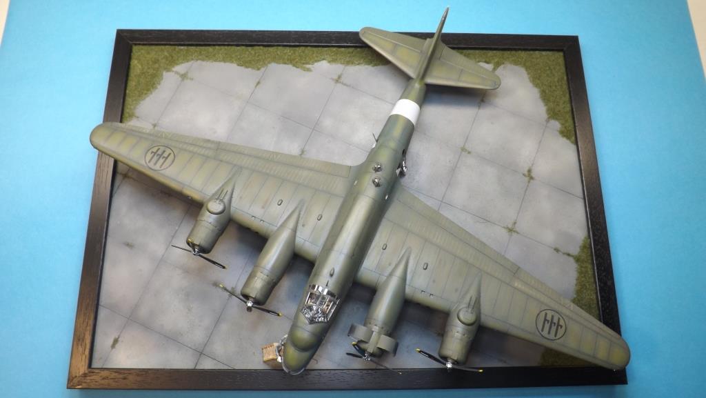
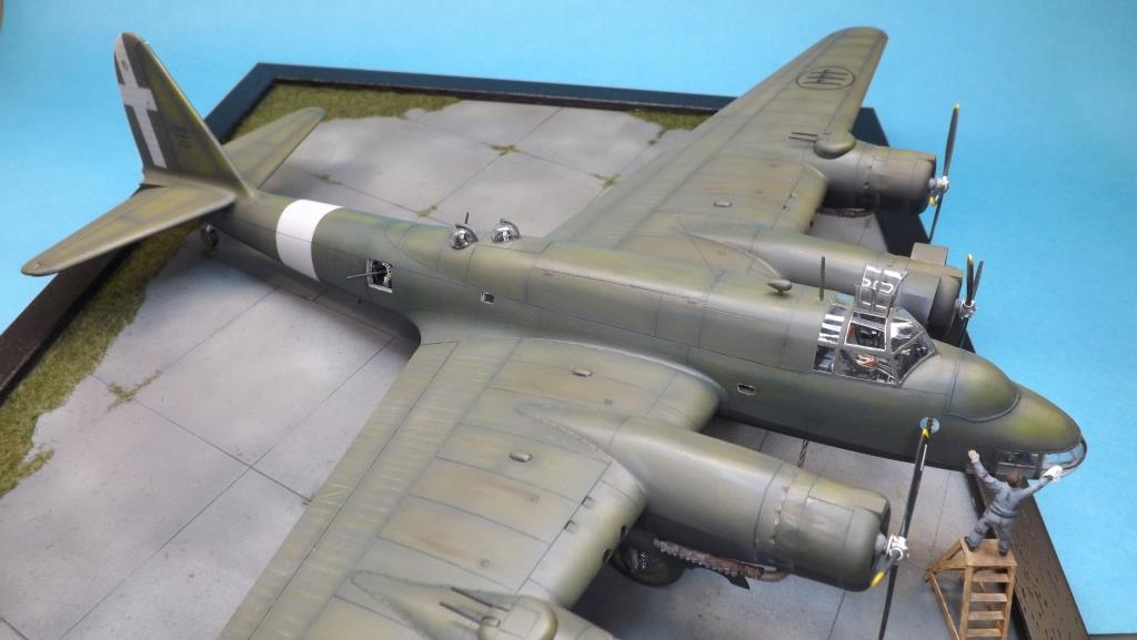
In 2005, Special Hobby produced a 1/72 Piaggio P.108B in the "gentleman scale" for
both production versions, Serie I and II SO72035:

I certainly didn't miss it and chose the latter version,
the one the nose gun removed. The box ended up among the others on my shelves, aware of the fact that if I had made it I would
have had to push myself with the detail also thanks to the documentation mentioned above. In the end I decided to get involved: it couldn't remain
unfinished, just gathering dust.
The kit is a short run type: there are no tabs for joining parts and these are not numbered on the sprues; trifles. On the other hand, the
dimensions and shapes are perfect compared to the scale drawings, so much so that I doubt whether Special Hobby used CMPR drawings; the transparent
ones are so thin and transparent that I believe it is impossible to do better with injection. The panels are exact and ultimately negative, apart from
some printing inaccuracies but nothing to worry about.
Construction
I start with half fuselages on which I intend to reproduce the internal infrastructure. The key to correct construction is given by the two bulkheads
that limit the bomb fuselage compartment and to which the main spars of the wings were joined. In the kit, obviously engineered to give the appropriate
robustness to a model which in 1/72 scale reaches considerable dimensions, the rear force bulkhead must be moved back by 8mm for correct allocation,
after having appropriately reshaped it, with consequent reconstruction of the slot for the leakage in the wings of the spars. Two other pieces are
supplied, which do not exist on the real model, one of which should be a bulkhead to be mounted immediately behind the pilots' seats; I’ve reused one,
after reshaping to create the front force bulkhead, while the other has been eliminated. The two bulkheads were therefore detailed with reinforcement
profiles, drilled where necessary and enriched - stuff for modelling zealots - with rivets by Archer decals.
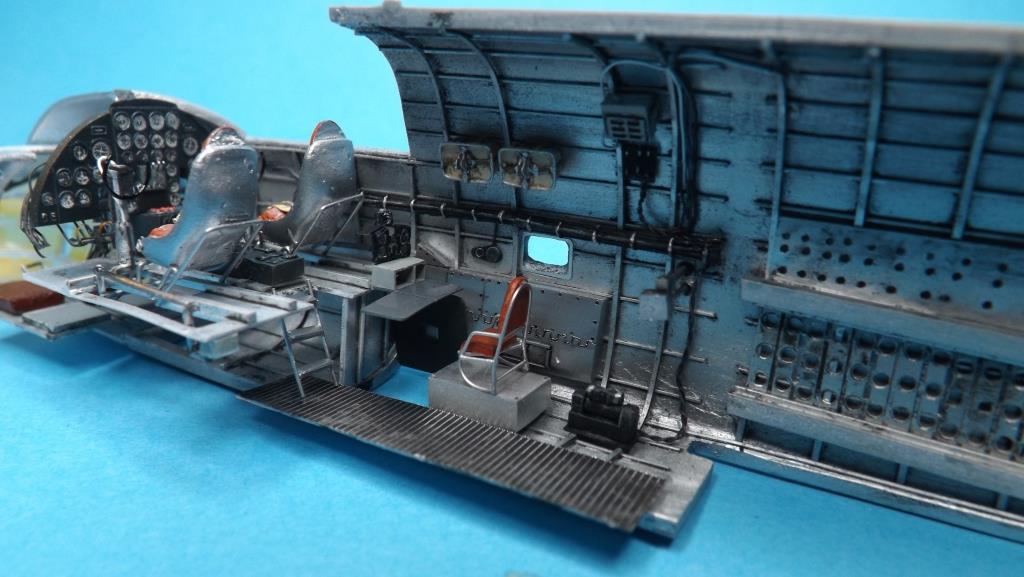
Behind the cockpit is the radio operator, on the left (port side), and the navigator, on the right (starboard side). Proceeding backwards you come
across the bomb bay (I am obviously referring to the B version - bomber) which, limited by the bulkheads, had a corridor in the center accessible
from the front and rear via ladders.
Note that a third force bulkhead was present at the tail, on which the non-retractable wheel was fixed. I haven’t mounted this.
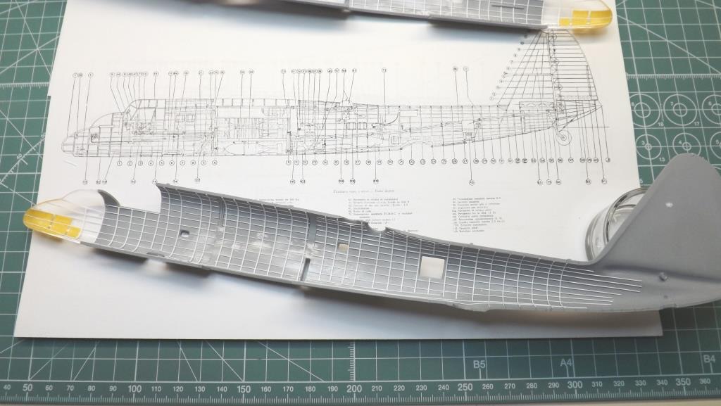
The internal walls of the two half fuselages of the kit present, as always happens, gaps with the external wing attachments, gaps
which I had to fill first with plasticard templates and then with putty, until continuity in the internal lines was obtained.
|
|
Breda Type G retractable turret with ammunition supply framework.
|
|
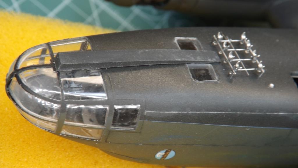
The entrance door to the fuselage on the left side and the ventral access hatch to the pilot cabin on the right side were therefore opened, the
only points from which to peek into the interior. Some missing details: the hole for the photoplanimetric machine was made aft of the Breda type "G"
retractable ventral turret, the spotlight immediately forward of the pilot cabin access hatch is missing and above all the ventral windows for the
pilots' use are missing. After having joined the two half transparent noses to the half fuselages, a long process of construction of the internal
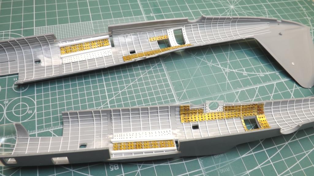
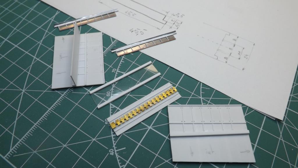
ribs with 0.3x0.3 and 0.3x0.5 plasticard profiles begins. In the central part of the fuselage, both in correspondence with the bomb compartment
and where the armorers were housed, there were reinforcement covers, perforated for lightening purposes. Their arrangement was anything but symmetrical,
not only due to the different allocation between right and left of the windows as well as the entrance door on the left. I reproduced them with
0.25 plasticard and using a photo-etched PSP set by Flightpath. It was a long, sometimes tedious job, every single piece must be measured and cut
taking into account the fact that they are two-dimensional parts placed on surfaces with different curvature gradients; I did my best.
The opening for the Breda G type extractable ventral turret must be enlarged. In fact, in the kit only the part that comes out when at rest is supplied in
transparent, but to correctly reproduce the interior of the fuselage and the turret itself requires this correction. I have not found much documentation
on this turret, only a few photos which however do not exhaust all my doubts regarding the actual structure, while for the Z type turrets located on the
engine fairings and the related domes for remote controls located in the fuselage there is nomenclature catalog for sale on the web.
All interiors are in Polished Aluminum Alclad. When airbrushing the front sight station, the high fluidity meant that some paint got under the
glazing masks: it happens. I corrected the mistake with the tip of a toothpick moistened with brake oil (any type/brand is fine); I leave it to act
for a few minutes and again with the tip of a toothpick I delicately remove the paint thus attacked by this fluid. Then with a cotton swab just
moistened with alcohol I clean everything up.
Cockpit
I should point out that the configuration of some cockpit installations is not definitively clear to me. In fact, in some photos, for example,
the gyrocompass is mounted on the central console, between the two pilots' seats, immediately under the instrument panel, while in other photos
and drawings it’s canonically positioned above; even the seats appear in some photos as having an enveloping armored backrest while in others this
is absent and they have comfortable upholstered armrests. Furthermore, the walls next to the two pilots appear differently equipped in various photos.
In short, a puzzle; all as evidence of the continuous improvements that were attempted to be made to the aircraft. I have two instruction manuals and
standards for assembly, adjustment, etc.: one for the first series for MMs from 22001 to 22008 and from 22601 to 22604 and the other for the second
series from MM 24315 to MM 24326; for many images and drawings one summarizes the other but there are many "dark areas" that remain. Already in the
manual of the first series in my possession there are many pages with extensive corrections by typewriter or even in pen, testifying to the continuous
improvements made. I had to make choices and my hope is that I didn't stray too far from reality.
The kit offers some resin parts such as the pilots' seats, the central console and the dashboard. The seats are valid for storage in “spare parts”;
initially I thought of using them but then I preferred to redo them, reprinting a resin seat taken from my spare parts. They were adjustable in height
and depth and were mounted on a tubular structure; the seat was made up of springs arranged in a radial pattern as the pilots sat on the parachute.
However, the photos of the manuals show some cushions that I reproduced. The floor of the kit is instead made of plastic but it is incorrect since it's
solid and does not have openings towards the compartment below: I preferred to completely redo this too. The control bars have been improved by adding
the balancer control link which passes, visible, under the floor; the flyers, supplied in resin from the kit, are too coarse, they were redone with the
addition of control chains and chronometers. The resin dashboard is excellent and 0.4 holes have been drilled on the back to then be able to insert the
electrical wires; however, the central console is decidedly inaccurate and I tried to improve it as much as the scale allows. Behind the dashboard, in
the lower part, the bars operated by the pedals have been added which, with the relative relaunches, operate the rudder. As stated in the aircraft's
instruction manual and regulations, all flight controls operate via control rods that run along the right side of the fuselage (that of the rudder also
along the left side), with the exception of the section between the two main bulkheads that delimit the bomb bay, along which they are external to the
fuselage itself, i.e. placed between the latter and the wing connection.
The kit does not provide any decals for the pilots' dashboard instruments; with the greatest possible approximation I used some old Reheat sets:
those who know them know that they show the instruments on a single decal sheet, so they have to be cut out one by one.
Immediately behind the central console there is the recess for the pilot cabin entrance which was accessed via a ladder.
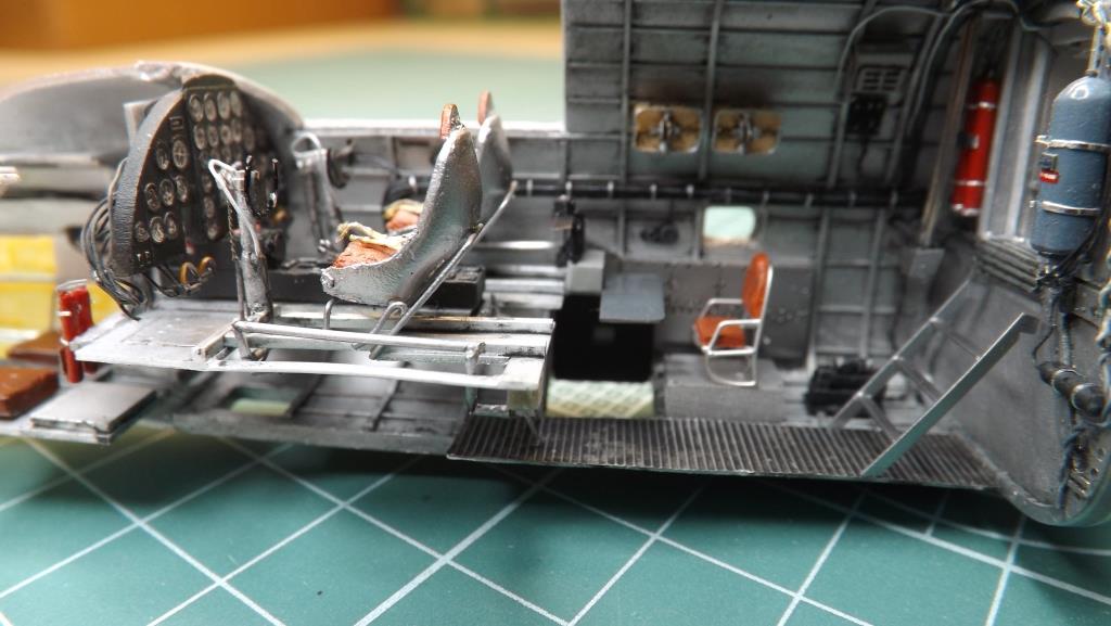
Radio and Navigator Stations
Immediately behind the pilot cabin there is the radio operator's station on the left and the navigator's station on the right.
All the radio operator's radio equipment has been rebuilt, with the exception of the two smallest ones taken from the Aires set for the Luftwaffe radios but which are perfect for the P.108, on a copper wire truss, in addition to the side panels/armor on in which, in the lower one, there is the wire antenna winding which was deployed through a tube, made with a syringe needle which will be mounted only during the finishing phase in order to avoid inappropriate breakages. In the first series this tube came out at the connection between the wing and the fuselage while during the production of the second series it was moved near the fairing of the left landing gear, externally, probably, I presume, so as not to interfere with the left hatch of the bomb bay when this one was open. Wanting to reproduce the serial number 24315, the first of the II version, I left the antenna tube in the position of the first version since in the manual of the II series it still appears in the fuselage. It will be moved later.
A folding table was built for the navigator's station (as well as for the wireless operator's station on which the telegraph key command was placed), the instrument panel and the gyrocompass. On the wall next to his station there was a metal cover inside which the flight control rods were protected, with the relative inspection panel.
Right under this station was the front access panel to the aircraft, with a small window. Only during the finishing phase of the model will the telescopic ladder be mounted. The L.S.R. servomotor was positioned immediately behind this station, which was also obviously rebuilt.
The seats, made of copper wire and plasticard for the cushions, were mounted on platforms. In the middle of the two stations, the walkway corridor was recreated with plasticard and aluminum for food use shaped on a knurled plastic for electrical use.
On the right wall there were also the two parachutes placed in special baskets. Having built the first one, I preferred to replicate it in resin since four are needed, two here and two for the engineer and the gunner in the central body of the fuselage.
The window frames were also redone with recycled photoetched spare parts.
For all the stations there were also sockets for the oxygen masks mounted on small squares on which the intercom was also present: for these too, the original piece was duplicated in resin; a total of ten are needed, one for each station.
The bulkhead leading to the bomb bay was equipped with the compressed air tank (on the right looking backwards) and the two buffer accumulator cylinders (on the left) of the Magnaghi system for trolleys controlling. Close to the bulkhead, the rod controls were rebuilt which remote controlled the Breda Z2 turrets located on the internal engine fairings from the fuselage domes. They ran over the side bomb holds and slipped into the wings and then reached the turrets.
A three-step ladder leads to the bomb bay while another two step ladder leads forward to the cockpit.
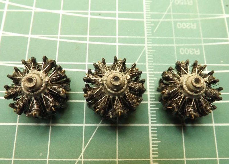
Engines
The P.108 was powered by four Piaggio P.XII RC.35s. They were 18-cylinder radial engines which, as mentioned above, were the real weak point of the aircraft in terms of reliability. Wanting to compare the Italian "Flying Fortress" with the American one, the B-17, the Piaggio engine had a power of 1350hp while the Pratt&Whitney R-1820 that equipped the Flying Fortress had 1200. This further demonstrates the greater performance, at least at the desk, of the Pontedera’s bomber compared to the major foreign competitors.
The kit offers 4 pieces with only the forward 9 cylinders: I left them where they were. To reproduce the engines from scratch (the panorama of detail sets regarding the Italian aircraft of WWII is bleak) I used an Aires 72-7009 set dedicated to the P&W R-2800 (late) as a basis; in it, essentially, you have the engine body, the cylinders (20) and other details. I started from the engine body, cutting it into various parts to obtain the two crowns on which the cylinders will be mounted and the one on which the air and fuel mixture deliveries to the cylinders were present. The front part, including the propeller hub, crankcase and pushrod distributor, was rebuilt with plasticard and spare parts. The cylinders were appropriately shaped on the heads as they were significantly different from the P&W ones.
Once the masters were made, I duplicated the pieces in resin.
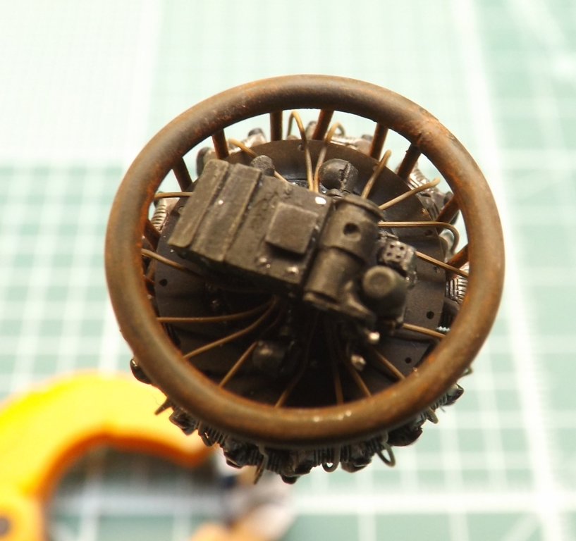
Obviously, the engine mountings are completely absent in the kit. This kit offers pieces with central holes for the wheels, to close the upper areas of the Landing gear bays. Thanks to the drawings in my possession they have been completely rebuilt, obviously those of the internal engines with the landing gears. Tanks were mounted on them, one on the side of which I confess I ignore the purpose, and one placed above: this was the engine oil tank. The firewalls are supplied by the kit and externally simulate the recesses for air venting, under the mobile flabella. Everything has been detailed to the maximum, especially for the engine which will remain uncovered in the model at the end.
The engine fairings need to be revised for a moment: they need to be thinned internally so as to fit perfectly with the engine nacelles and the connection of the upper air intakes needs to be reviewed. The one relating to the uncovered engine has also been detailed internally with perforated structures to protect the tube that goes from the upper air intake to the carburetor, simulated with soldering tin wire.
The four engines were detailed, again a long and tedious job, with constantan wires (taken from old wire resistors for electrical circuits) to simulate the electrical connections that went from two control units located at the front to each cylinder. Then the wires for the spark plugs are inevitable. The valve rods ran from the front crankcase to the front bosses of each cylinder. Suffice it to say that there are 4 engines and each has 18 cylinders: the calculation is easy. The front covers are resin replicas of a home-built one; don't forget the mechanism for adjusting the propeller pitch. The blades and related hubs are those supplied by the kit.
The engine which remains visible has also been detailed in the rear part with the relative pipes that go towards the landing gear bay. The exhausts and pipes that convey the mixture to each cylinder were also added to it. The engine fairing was obviously worked by removing the areas relating to the panels that will remain open, made of tin foil (see the drawing on the special CMPR for the correct degree of opening). Finally the exhausts: each is supplied by the two-piece resin kit; one curved and one that simulates the flame-retardant Wellington-type exhaust. Unfortunately, a part between the two is missing and was rebuilt with copper wire wrapped on a tube of adequate thickness. During the finishing phase, the hooks that fastened the exhausts to the engine nacelles will be mounted.
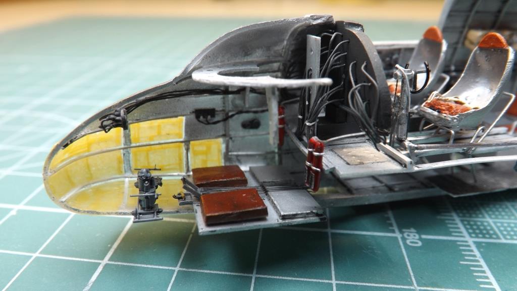
Bomb targeting system
Located in a glass nose from which a pointer sighted the target and commanded the bomb release. This happened, in Serie II, thanks
to an electrical circuit controlled by a Siemens control unit which replaced the pneumatic system of Serie I planes, operated by a lever panel located on the
left side of the workstation. In both Serie there was an auxiliary mechanical release system that could be operated using a handle placed on the floor
and a series of levers that controlled the individual releases via cables running on the floor. Having chosen to reproduce a Serie II example, I rebuilt
the control unit. In Serie II, the compressed air cylinders, always positioned on the left side, at the back of the workstation, were consequently also
absent.
The aiming took place thanks to a Jozza U.3 that I scratch built; it was mounted on the lower central beam.
On the right wall, only in Serie I, there were the ammunition box for the front machine gun and the shell bag; in my model these parts were not reproduced:
I reconstructed the support structure of the nose on which the Serie I machine gun rested. There was also on the right the control for operating the camera
located at the back of the fuselage. In the upper part of the station, centrally, there was the pointer's dashboard, obviously rebuilt like the floor since
the one supplied by the kit is a fantasy one.
At the back of the station, and therefore behind the dashboard of the pilot cabin, were mounted the four extinguishers for the engines' fire prevention
system.
Landing gear and wheels
The ones offered by the kit are not exactly the best. The tail wheel is more than sufficient with the leg supplied in resin but the main landing gears are crude to say the least. On the other hand, they have to support the weight of the model and I therefore did not venture into self-builds that could have compromised the overall robustness. I therefore limited myself to improving the parts by flattening, for example, the upper parts of the crossing reinforcement structure. The fixing of the main legs to the wheels recalls solutions from the 1960s, requiring them to be widened to fit the fixing pins into the wheel holes: these pins were eliminated by drilling the hubs and wheels and then inserting a small steel tube: everything is more robust and truthful.
The missing tubular structures for the landing gear closing and the fixing points of the landing gear bays have been added, as well as obviously all the pipes present.
The wheel rims are as far from reality as ever: barely sketched. With recycled photoetched parts and plasticard I created the master and then duplicated it in resin.
The landing gear doors have been improved with lightening holes on the internal walls.
Bomb bay
I didn't have adequate documentation: photos, none; there are some drawings which however did not provide me with a correct three-dimensional view of the details. From the interior photos you can glimpse the central corridor and the ceiling but nothing in perspective regarding the mechanisms for fixing and releasing the bombs. I therefore limited myself to reproducing this area as best as possible by choosing to leave the central compartment closed, the one that was closed with a wavy shutter. The side doors of the bomb bay were instead reproduced open, made with tin/lead sheet, copper wire and plasticard.
Lastly, given the piece fragility, I mounted the Jozza collimator in the front aiming position and after months of self-construction and detailing I closed the half-fuselages. Often, during this period of time, I carried out closure tests to check that everything fit together correctly and that some pieces did not fall off.
The pilot cabin lens was then mounted after removing the areas relating to the upper opening windows for rapid abandonment of the aircraft. These were reproduced in thermoformed acetate and will be mounted during the finishing phase with the S-shaped support rods. The adaptation of the lens to the fuselage required the application of various types of filler and relative sanding.
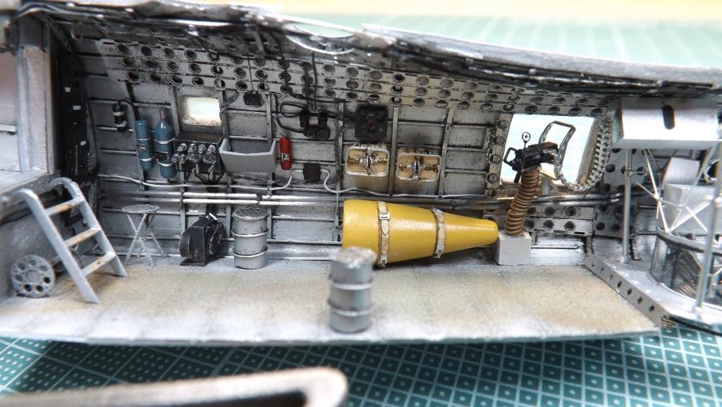
The Engineer and machine gunner's station
Here too you have to build everything from scratch. I started with the engineer's instrumentation: two large panels on the rear face
of the bulkhead that separates this area from the bomb bay. In the middle, the access ladder to this room was rebuilt and under it the
rolling shutter mechanism that closed the central part. On the right side all the instruments have been reproduced, such as the engine start
panel, the blow counter of the Z.2 turrets, as well as the compressed air and air filter and fire prevention extinguishers; the starter motor
placed on the floor could not be missing. The folding stool for the engineer has also been redone. Also on the right side are the two parachutes
and an inflatable boat obtained from an additional tank from my spare parts. Running along the side are the rod controls for the tail rudders which
were actually sections connected to each other by cardan joints.
On the left side there are the oxygen cylinders and the first aid box located immediately next to the entrance.
Here too there are sockets for oxygen masks and intercom for each occupied position.
On both sides there were staggered openings for the machine guns. I used an Aires set dedicated to the 7.62 Brownings which, with some modifications
and details, simulate the Breda ones very well. The machine guns will only be mounted during the finishing phase. The ammunition boxes, located above,
have obviously been rebuilt, as have the case collection boxes, located on the floor, and the related flexible conveyors. The ammunition belts come
from an Eduard set also dedicated to 7.62 Brownings. The machine gun supports were instead taken from a Mister Kit set dedicated to the CANT Z.1007:
they are perfect in design and size.
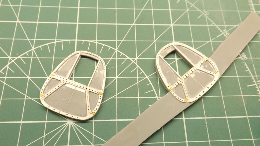
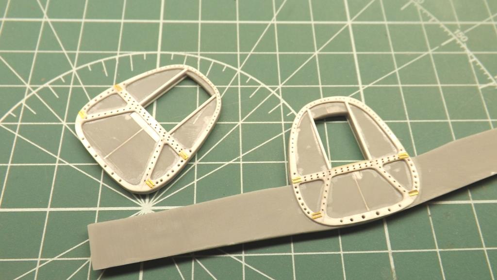
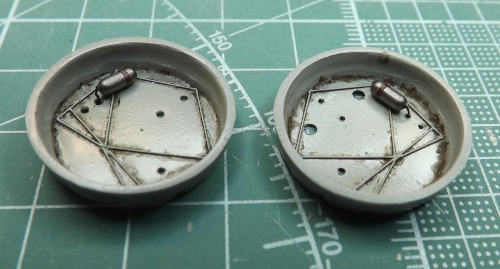
The Breda Z.2 turrets control stations are supplied with resin parts: comparing them with the nomenclature catalog they seem a bit imaginative. I didn't
discard them but added recycled photo-etched parts, plasticard, etc. On the other hand, the transparent domes and the resin support that allowed the
rotation of the turrets are excellent. To allow the machine gunners to reach these positions mounted on the top of the fuselage, there were risers
(I don't know how best to define them) consisting of a sort of bins with a non-slip surface on the upper part. I can't imagine anything more uncomfortable
during operational use; they were also reconstructed, one in original and the other duplicated in resin, and positioned on the floor.
|
|
|
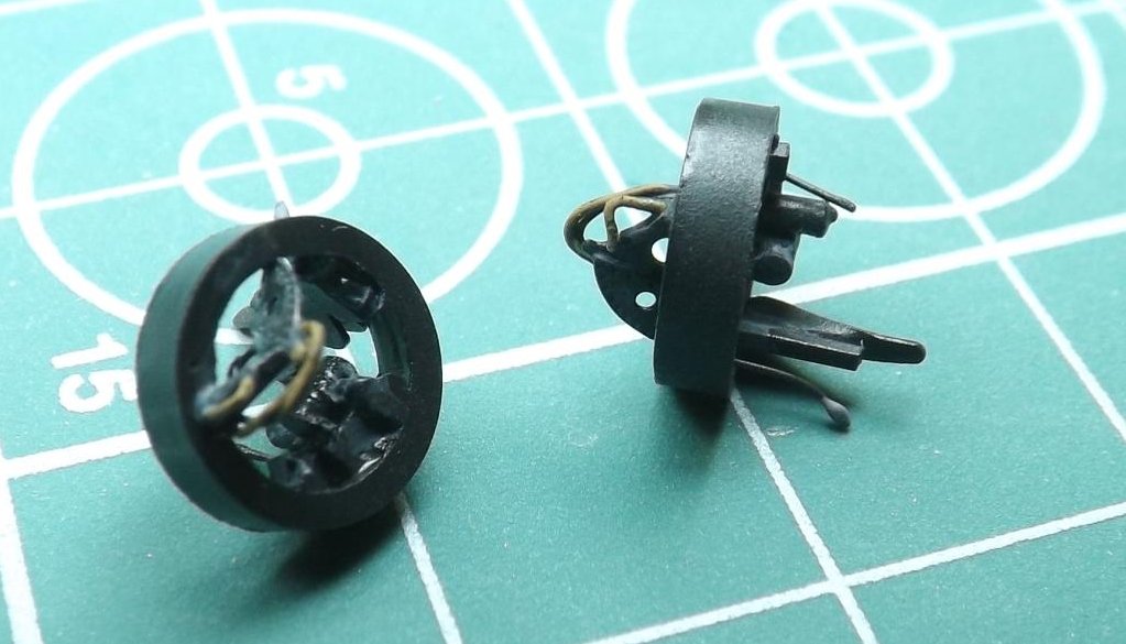
Remote controlled Breda Z2 turret
|
|

|
|
Breda remote controlled Z2 turret; 2 x Breda SAFAT 12.7 mm.
|
|
Yes, the floor, of course: it was also redone in plasticard with the rivets that can be seen in the original photos.
Finally, the various caves and pipes created following the photos in the manuals are inevitable.
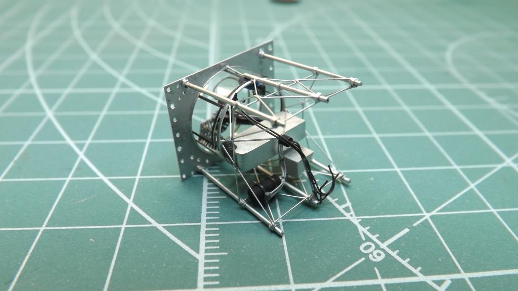
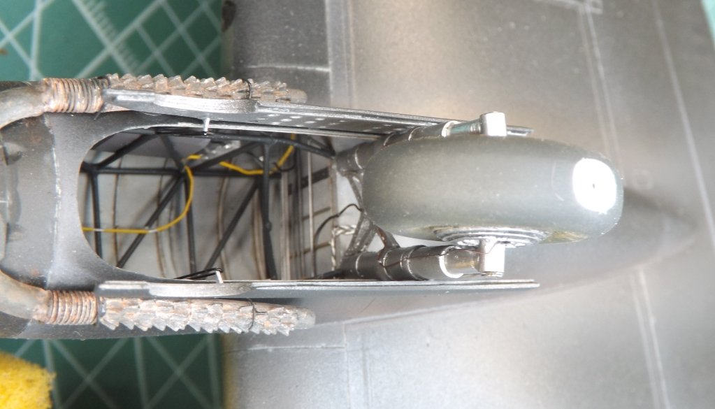
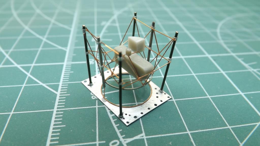
The Breda type G turret: this complex was located in the rear part of the fuselage for the ventral defense. It consisted of a metal infrastructure that allowed the extension and retraction of the turret itself thanks to two hydraulic jacks; the movements of the weapon, for swinging and elevation, were controlled via two levers which activated two oleo-pneumatic motors. The weapon, a 12.7mm Breda SAFAT, was equipped with 450 rounds and the machine gunner sat on the bottom of the turret (here too comfort was not foreseen). The turret must be represented in the closed position otherwise it will hit the ground. The framework was rebuilt with copper wires and pieces of syringe needle; the ammo crate with a resin piece. As mentioned, the kit offers only the lower part with a transparent piece. This has been lowered by a couple of millimeters since in the closed position only the curved dome remains visible while the transparent cylinder retracts completely; this one was made with thermoformed transparent acetate (heated over a flame and wrapped while still soft on a cylinder of the appropriate diameter). The slit from where the machine gun barrel came out was created on the dome supplied by the kit. Inside I inserted the cartridge case and a cushion (two-component putty) for the machine gunner.

|
|
Breda retractable G1 turret; 1 x Breda SAFAT 12.7 mm.
|
|

|
|
Waist emplacement; 1 x Breda SAFAT 7.7mm (later 12.7 mm).
|
|
More details
Then it was the turn of a toilet and a small sink complete with a water tank placed on the ceiling, pipes and drain. These installations were placed over the Breda type G turret: a bulkhead gave some privacy.
Further astern, the camera was installed, mounted on a metal pylon, to estimate the damage caused by the bombing action.
Wings
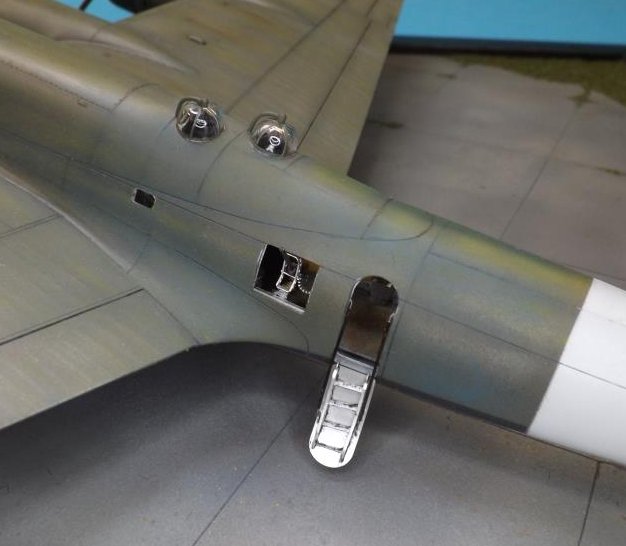
First of all, the internal parts of the trailing edges were thinned as more as possible and then the upper parts were joined to the lower ones. On the wing leading edges, the air intakes for the oil radiators which are not supplied by the kit must be improved, thus leaving a nice hole in evidence. They were then rebuilt: here too, once one was made the other three were replicated in resin.
The landing lights were placed between the external engines and the high-support wings. The kit represents them full. The recesses were closed with plasticard were therefore created; the transparencies were thermoformed by adding the lights by a 2mm AK Interactive set. The transparent parts were then surrounded by thin decal strips painted with Olive Green.
The most complex parts to adapt are the internal engine fairings. As mentioned, the kit is a short run type so the accuracy of the shapes may not find its place. Delicate and progressive sanding was therefore necessary to adapt them as best as possible with subsequent filling and new sanding to make everything smooth and streamlined. The internal ones, which house the landing gear bays, have been detailed internally to simulate the structural ribs.
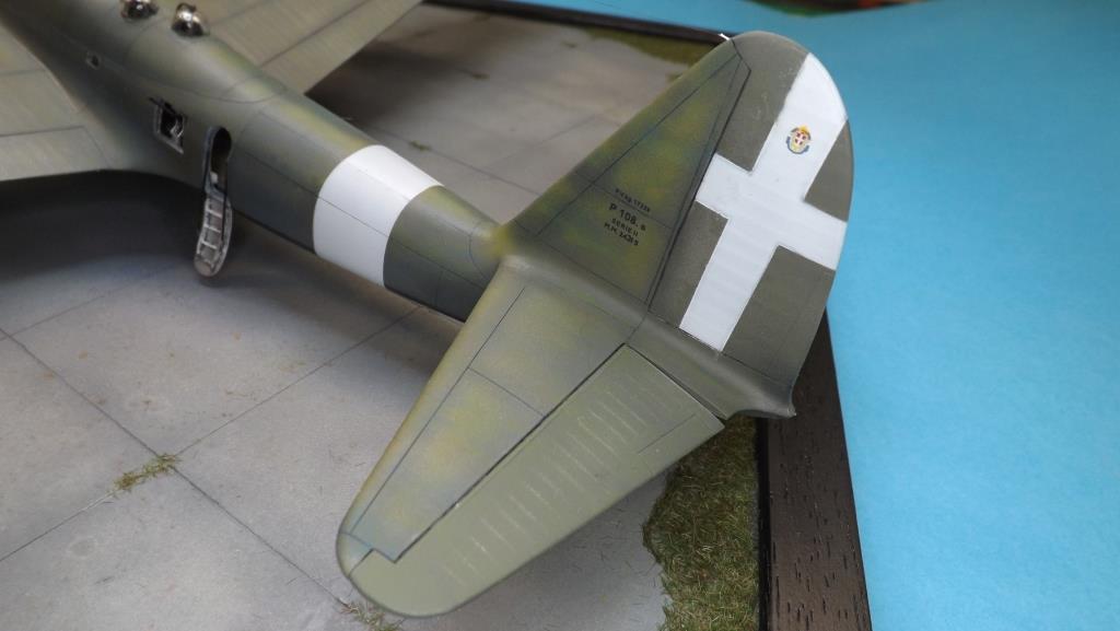
At the tail, the horizontal rudders were detached and repositioned slightly lowered in order to give a minimum of movement to the model.
Painting
AK Interactive Primer and Microfiller was first spread over the entire model to highlight any imperfections.
Camouflage started from the lower surfaces. These are in Tamiya Smoke Black. In the profile of CMPR special issue it is reported that the lower wings insignia of this aircraft were darkened in an unspecified dark grey, I presume the Dark Blue Gray as mentioned in the famous Table 10 issued by the DGCA and distributed in the first half of 1942. Stop given the authoritativeness of all the CMPR works, I had a sincere doubt regarding this obliteration. In fact, there are photos available in which, with the original camouflage still on, these insignias were actually darkened in gray but when probably the beams and the outline were in black on a white background (otherwise it would have not sense). In fact, it was with a circular dated 29 October 1941 from the DCA of Turin that the abandonment of the white background for the wing insignia was regulated in favor of the underlying camouflage. Question: Why darken all the bottom surfaces and leave these discs gray? I was unable to give myself a logical answer even taking into account that the plane dates back to 1942 when the DGCA directives were now starting to be implemented by the aeronautical factories (see Colors and camouflage schemes of the Regia Aeronautica 1935-1943 by Postiglioni - Degl'Innocenti ). At the risk of committing a false model with respect to the CMPR profile, I therefore preferred not to apply these obliterations in grey, leaving all the lower surfaces in black which I assumed had been applied subsequently.
Some doubts, however immediately overcome, regarding the propellers. You can see many photos of the Series I with the blades in Light Blue Gray as well as many others with the blades in black with yellow tips. Here too I used a temporal criterion: since it was an aircraft from 1942 I painted them in this latter configuration. This is also supported, in my very modest opinion, by the fact that it is an aircraft for night operations.
A sort of modulation was applied to the panels: only one side of them, in a very nuanced way, so as to have an aging but not a strong one given that the application of the carbon black was recent. With the same grey, very light shades were then given in the relative direction of the wind: I wanted to avoid a monotonicity of the lower surfaces without exaggerating.
On the upper surfaces, before the camouflage colour, the paneling, the reinforcement lines and those separating the mobile surfaces were highlighted with black.
Given that the very few photographs of operational aircraft denote premature aging of these surfaces, I wanted to pre-shade the panels with different colors depending on the area of the aircraft: for example, yellow was applied on the external wing panels and on the upper areas of the fuselage and engine fairings (almost a zenithal application) while with blue I darkened the lower areas and those in correspondence with the engines. I limited myself to these two colors which are the primary ones from which green is obtained, without using others such as white or brown or even other greens, which in the end, in my opinion, would have caricatured Olive Green too much: it's okay to age, but according I need criteria.
Dark Olive Green (Mr. Hobby 17 – RLM 71) was then applied with progressive passes, each partially covering the pre-shading done previously, until a result that seemed adequate to me.
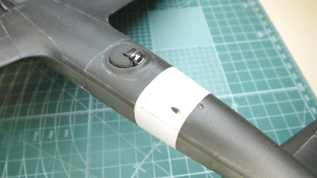
Finally, the fuselage band and the Savoy cross on the tail were made with an off-white / very light grey, packaged specifically.
The entire model was "caramelized" with transparent gloss varnish. Once the decals (very few) were applied, another series of coats of transparent gloss varnish were given. Aging can thus begin.
On a model of such large dimensions, there is a risk of flattening the camouflage and at the same time an exaggeration that does not correspond to reality. Balance is needed.
I then resumed, on the upper surfaces, the motifs of the pre-shading applied previously: with yellow and blue oil colors I applied small dots here and there; yellow on the most exposed areas, blue on the lower and darker ones. When these colors are still fresh, but not too fresh, with a flat brush, but also with cotton swabs of different sizes, streaks were made in the direction of the relative wind, removing a good part of the color. I tried to achieve a barely noticeable result in order to give discontinuity and credibility to the camouflage colour. Very light brown dots were applied in the engine areas while more or less shaded trails were applied near the fuel refueling doors.
The panels were then coated with gray for the lower surfaces and very dark green for the upper ones (PLW MIG).
A few coats of AK Interactive's Ultra Matte Varnish (oil colors allow some gloss to shine through with traditional matte clearcoat) sealed everything.
For aging on the matt I limited myself to a drybrush on the canvas parts of the wings and tail rudders in order to bring out the structure well reproduced by the kit.
Still on the matt, I created the trails of the engine exhausts with light grey, brown and black passes of increasing width and intensity. Here too without exaggerating.
Finishing touches
At the end, landing gears and wheels with related brake pipes are mounted; the fuselage access door, made of sheet metal and plasticard, with the relative closing cords; the street lights were made up of bulbs that protruded from the wing edge: I reproduced them with 0.75mm resin rivets painted in silver and transparent colors, while at the tail the white light was made with a die-cast transparent. The machine gun mounts of the wing turrets, of the lateral and lower positions come from a Master set actually dedicated to the B-17 but are perfectly suited to simulating the Breda-Safat. Finally the last pieces: ventral access ladder, ventral rack for the devices, the radio direction finder bulb and the main antenna rod with its extension towards the tail empennage. The lower beam that extends below the pointer cabin has been redone with a piece of resin as the one in the kit is 8mm shorter than the necessary dimensions. The lower windows that were used by the pilots to sight the target have been reproduced in acetate. In the fuselage, near the toilets, a fairing has been placed to drain liquids. The tube with the wire antenna is placed laterally on the left, immediately in front of the bomb bay. Finally, the Pitot tube, placed laterally to the pointer station rather than in front of the I series, was made with plasticard and copper wire.
Conclusions
More than a year and a half of much, much work which perhaps in the end can certainly be missed by an inattentive glance but it doesn't matter. I am always of the opinion that a model is a scale reproduction of a subject that actually existed and the final result satisfies me personally.
I would like to thank again the Piaggio Historical Office, in particular in the person of the engineer Tarrini who at the provided me with extensive
documentation without which I could not have built such a model.